How to Choose an Embedded Thermal Module?

Time:2026-10-23 Author:Oliver
0%

Choosing an Embedded Thermal Module is a practical engineering decision, not a simple catalogue search. The correct unit must match the system’s heat load, enclosure size, airflow, power budget, and operating environment. A module that performs well on a laboratory bench may struggle inside a sealed cabinet at 45°C. Small details matter.

Experienced engineers usually begin with measured thermal data rather than optimistic estimates. Record the component’s actual heat output, surface temperature, duty cycle, and nearby heat sources. Check whether the module supports conduction cooling, forced airflow, or liquid cooling. Review the thermal interface material, mounting pressure, connector layout, control method, and maintenance access. These details often decide long-term performance.

Reliability also depends on evidence. Examine supplier test reports, operating limits, failure-rate information, and relevant quality certifications. Ask how the Embedded Thermal Module behaves during vibration, dust exposure, voltage variation, and repeated thermal cycling. A thermal camera can reveal uneven contact or unexpected hot spots during prototype testing. Still, one test is not enough. Real installations often expose assumptions that simulations miss.

Cost deserves careful judgment. A cheaper module may require larger fans, stronger brackets, or more frequent service. A premium option may exceed the project’s needs. The best choice balances cooling capacity, noise, efficiency, integration effort, and service life. Engineers should document each decision and leave room for redesign. Thermal performance changes when the enclosure, workload, or surrounding temperature changes. Good selection remains evidence-based, cautious, and open to correction.
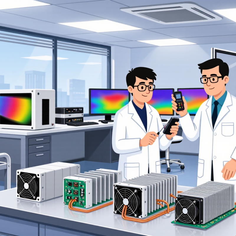
How to Choose an Embedded Thermal Module?

What an Embedded Thermal Module Is and How It Works

An embedded thermal module is a compact system built into equipment to control heat. It usually combines a heat-transfer surface, sensor, controller, and cooling or heating element. Its purpose is simple: keep sensitive components within a safe operating range.

The module detects temperature through a sensor placed near the heat source. The controller compares the reading with a programmed target. It then adjusts airflow, liquid circulation, heating power, or cooling output.

For example, a sensor may detect rising heat around a processor, while a fan increases speed within seconds. Selection requires attention to thermal load, available space, response time, noise, and power use.

Installation experience matters too. A technically efficient module can still perform poorly if airflow paths are blocked or contact surfaces are uneven. I have found that real operating conditions often differ from laboratory figures. That detail is easy to underestimate.

Tips:

Measure peak heat, not only average heat. Check the module’s operating range and sensor accuracy. Leave room for maintenance and cable routing.

Test performance under dust, vibration, and changing ambient temperatures. Also question the first design choice.

A smaller unit may save space, but it could create unstable temperature swings. A larger unit may offer reliability, yet consume unnecessary power. Record actual temperature data before making a final decision.

Which Operating Conditions Shape Module Selection

Choosing an embedded thermal module starts with operating conditions, not cooling capacity alone. A module rated for 200 watts may fail in a sealed enclosure at 45°C ambient. Measure the real environment. Record temperature, humidity, airflow, dust, vibration, and available voltage. These details often matter more than headline wattage. Keep margins practical. Thermal estimates are never perfect.

Map the heat load across time. A processor may draw 80 watts during boot, then settle near 35 watts. Short peaks can demand different control behavior than continuous loads. Check the module’s thermal resistance, response time, and maximum case temperature. Also inspect the mounting surface. A thin aluminum wall, uneven pad, or loose fastener can add hidden resistance. Test the complete assembly, not only the module. That is where surprises appear.

Airflow changes selection quickly. Natural convection may work on a bench but fail inside a cabinet. With forced air, verify fan direction, filter clogging, noise, and failure response. In humid locations, condensation deserves attention. In mobile equipment, vibration and shock can weaken interfaces over time. I once trusted a clean laboratory result too much; field dust changed it. Recheck performance after aging, blocked airflow, and power variation. Choose monitoring points for temperature and alarms before production. Small gaps in the plan become expensive later.

How to Match Cooling Capacity with Heat Load

How to Choose an Embedded Thermal Module?

Choosing an embedded thermal module starts with the actual heat load, not the advertised cooling capacity. Estimate heat from the processor, memory, regulators, and power conversion losses. Measure the system during demanding workloads, not only during startup. A module rated for 100 watts may remove far less inside a sealed enclosure. Ambient temperature, airflow, mounting pressure, and dust all reduce available performance. Keep the expected junction temperature below the component’s specified limit. Leave practical thermal margin.

Thermal resistance helps connect heat load with cooling capacity. Use the equation Rθ = (Tj − Ta) / Q where Q represents total heat in watts. For example, a 60-watt load may require less than 1°C/W under specific temperature limits. Check every layer, including interface material, spreader, module, and enclosure. Small gaps can create large temperature increases. The peak load also matters. Short bursts may exceed the continuous rating, even when average power looks acceptable.

Validation should include sensors placed near the hottest components. Test at the highest expected ambient temperature and with restricted airflow. Log temperatures over time. Infrared readings can mislead when surface emissivity is unknown. A contact sensor is often slower, but useful for comparison. The first calculation is rarely perfect. That is normal. In practice, engineers sometimes discover uncounted losses after testing. Recheck the power budget, mounting pressure, and fan curve before changing the module.

How to Compare Form Factor, Materials, and Integration Options

Choosing an embedded thermal module starts with the enclosure, not the heat sink. Measure the available height, airflow path, mounting holes, and service clearance. A 30 mm module may fit mechanically but block a nearby connector. ASHRAE TC 9.9 recommends 18–27°C for many air-cooled electronics environments. That range sounds comfortable, yet sealed enclosures can exceed it quickly. The International Energy Agency estimates that data centres consumed 240–340 TWh of electricity in 2022, showing why efficient heat removal matters beyond component reliability.

Materials change both thermal performance and weight. Copper spreads heat well, while aluminium reduces mass and cost. A graphite layer can help distribute heat across uneven surfaces, but it may need electrical insulation. Check thermal resistance under the actual clamping pressure, not only the supplier’s laboratory condition. JEDEC JESD51 methods provide a useful comparison framework, although real embedded systems often have tighter airflow and smaller contact areas. My first design choice is sometimes wrong: maximum conductivity does not always mean the best system result.

Tips: Compare the module’s thermal resistance, thickness, contact pressure, and operating temperature together. Test it inside the final enclosure. Use thermocouples near the hottest component and connector. For integration, evaluate passive, fan-assisted, and liquid-assisted options early. A replaceable fan may improve peak cooling but increase noise and maintenance. A passive module may be quieter, yet it can require a larger metal chassis. Leave tolerance for aging, dust, and imperfect assembly.

How to Choose an Embedded Thermal Module? - How to Compare Form Factor, Materials, and Integration Options

Typical engineering comparison ranges for embedded thermal module architectures. Actual performance depends on heat load, airflow, mounting pressure, interface materials, and enclosure design.
Module Option Typical Form Factor Typical Materials Indicative Thermal Performance Integration Options Main Advantages Key Limitations Best Fit
Flat Conduction Plate Low-profile plate; commonly 3–12 mm thick, with a footprint matched to the heat source. 6061 aluminum, copper, or aluminum with a copper heat-spreading insert. Approx. 0.2–2.0 °C/W from heat source to mounting surface, depending on size and interface quality. Direct chassis contact, bolted heat spreader, thermal pads, graphite sheets, or remote heatsink connection. Compact, mechanically simple, low cost, and easy to seal inside an enclosure. Limited surface area; performance depends strongly on chassis conductivity and contact pressure. Low-to-moderate heat loads in sealed or space-constrained equipment.
Finned Air-Cooled Module Extruded or bonded-fin assembly; typical height 20–80 mm, with fin spacing of about 2–8 mm. Aluminum base and fins; copper base inserts may be used for localized heat spreading. Approx. 0.1–1.0 °C/W, highly dependent on airflow velocity and fin geometry. Natural convection, forced-air fan, ducted airflow, spring clips, screws, or board-level mounting hardware. High heat rejection for its mass; widely available manufacturing processes. Requires airflow clearance; fans add noise, power consumption, and a potential maintenance item. Moderate heat loads where airflow is available.
Vapor Chamber Spreader Very thin planar spreader; commonly 2–6 mm thick and available in custom rectangular shapes. Copper envelope and wick structure with a sealed working fluid, commonly water for electronics temperature ranges. Effective in-plane conductivity can exceed 500 W/m·K; total thermal resistance is application-dependent. Placed between a concentrated heat source and heatsink, chassis plate, or fin array. Spreads localized heat efficiently while maintaining a thin profile. Higher cost; orientation, bending limits, flatness, and mounting pressure must be controlled. High-power processors or compact designs with localized hot spots.
Liquid Cold Plate Machined, brazed, or friction-stir-welded plate; commonly 8–30 mm thick with integrated channels. Aluminum or copper body, stainless-steel fittings, and compatible seals or manifold components. Approx. 0.02–0.2 °C/W at the cold plate, depending on flow rate, channel design, and coolant temperature. Pump, reservoir or cold-loop connection, hoses, quick-disconnect fittings, and leak detection. High heat-removal capacity with relatively uniform component temperatures. More components, higher integration effort, leak risk, and added system cost. High-power embedded systems and sealed environments with limited air cooling.
Graphite Heat-Spreading Layer Flexible or semi-rigid sheet; commonly 0.025–0.5 mm thick. Pyrolytic graphite, often laminated with polymer films, adhesive layers, or protective coatings. In-plane conductivity may range from about 300 to above 1,000 W/m·K; through-thickness conductivity is much lower. Applied to enclosure walls, battery packs, circuit boards, or between a heat source and spreader plate. Extremely thin, lightweight, flexible, and effective for reducing surface hot spots. Does not independently reject heat; requires a receiving surface or secondary heatsink. Thin portable electronics and uneven heat-distribution problems.
Chassis-Integrated Thermal Wall Structural enclosure wall or baseplate; thickness commonly 3–15 mm in the thermal path. Cast or machined aluminum; copper inserts, heat pipes, or graphite layers may be added locally. System-level performance commonly falls in the 0.3–2.5 °C/W range, depending on external convection. Direct component clamping, thermal gap fillers, external fins, mounting ribs, or conductive enclosure panels. Combines mechanical protection, electromagnetic shielding, and heat rejection in one structure. Thermal performance is constrained by enclosure orientation, ambient conditions, and external surface area. Rugged, sealed, and space-constrained embedded equipment.
Selection checkpoints: confirm the allowable component temperature, total heat load, peak heat flux, enclosure airflow, available mounting area, material compatibility, interface pressure, serviceability, and required ingress-protection level before finalizing the module architecture.

How to Evaluate Reliability, Efficiency, and Total Cost

How to Choose an Embedded Thermal Module: Evaluating Reliability, Efficiency, and Total Cost

Reliability begins beyond the advertised MTBF figure. Test thermal cycling, vibration, humidity, and repeated start-stop conditions under realistic loads. IEC 60068 environmental methods provide a useful testing framework. ASHRAE TC 9.9 guidelines also help define acceptable operating temperatures for electronic equipment. A module should include protection against sensor failure and blocked airflow. That detail matters.

Efficiency is not simply low power consumption. Measure cooling capacity, response time, noise, and performance at partial load. The IEA’s Electricity 2024 report estimates data centers used about 460 TWh globally in 2022. Demand could exceed 1,000 TWh by 2026. Even a small efficiency loss becomes expensive at scale. U.S. Department of Energy guidance also identifies cooling as a major data-center energy load. Compare watts removed per watt consumed, not only the catalog rating.

Total cost includes installation, controls, filters, maintenance, replacement labor, and downtime. A cheaper module may require extra brackets, software, or field calibration. That weakness is easy to miss. Build a three-year cost model using measured energy data and local service rates. I would also question perfect laboratory results. Real cabinets collect dust, airflow changes, and operators make mistakes. Pilot testing under those conditions often reveals the most useful answer.

FAQS

What is an embedded thermal module?

It is a compact system built into equipment to control heat. It may combine a sensor, controller, heat-transfer surface, and cooling element. Its goal is simple: keep components within a safe temperature range.

How does an embedded thermal module control temperature?

A sensor measures heat near the source. The controller compares that reading with a programmed target. It then adjusts airflow, liquid circulation, heating power, or cooling output. For example, a fan may speed up within seconds. That response can still vary.

How should cooling capacity match the heat load?

Start with the actual heat load, not the advertised rating. Include processors, memory, regulators, and power losses. Measure demanding workloads, not only startup conditions. A module rated for 100 watts may perform worse inside a sealed enclosure. Measure peak heat.

What thermal resistance calculation is useful?

Use Rθ = (Tj − Ta) / Q. Rθ represents thermal resistance, while Q represents heat in watts. A 60-watt load may require less than 1°C/W under specific limits. Check every layer, including interface material and enclosure paths. Small gaps matter.

Which operating conditions should testing include?

Test at the highest expected ambient temperature. Also test restricted airflow, dust, vibration, and changing temperatures. Place sensors near the hottest components. Log temperatures over time. Laboratory figures may not match field conditions.

How can physical size affect module selection?

Measure enclosure height, airflow paths, mounting holes, and service clearance. A 30 mm module might block a nearby connector. Leave space for cables and maintenance. A smaller unit saves space but may create unstable temperature swings. Compact is not always better.

Which materials are commonly considered?

Copper spreads heat effectively but adds weight. Aluminium reduces mass and cost. Graphite can distribute heat across uneven surfaces. It may require electrical insulation. Check performance under actual clamping pressure, not ideal laboratory pressure.

Should the design use passive, fan-assisted, or liquid-assisted cooling?

Passive cooling is quiet and may use a larger metal chassis. Fan-assisted cooling can improve peak performance but adds noise and maintenance. Liquid-assisted systems may suit higher heat loads and tighter spaces. Compare all options inside the final enclosure. My first choice may be wrong.

Conclusion

Choosing the right Embedded Thermal Module begins with understanding how it transfers heat, regulates temperature, and supports the performance of the target system. Selection should be based on operating conditions such as ambient temperature, airflow, humidity, vibration, available power, and space limitations. These factors determine whether the module can maintain stable operation under normal and peak workloads.

The cooling capacity must be matched to the system’s actual heat load, including safety margins for changing conditions and future demands. Designers should also compare form factor, material compatibility, mounting methods, electrical connections, and ease of integration. Beyond initial specifications, reliability, energy efficiency, maintenance requirements, and total cost of ownership are essential considerations. A well-chosen Embedded Thermal Module should deliver consistent thermal control while fitting smoothly into the overall design, minimizing energy use, reducing operational risks, and providing dependable performance throughout its expected service life.


Oliver

Oliver

Oliver is a seasoned marketing professional with a wealth of expertise in driving brand awareness and engagement. With a deep understanding of our company's product offerings, he consistently delivers high-quality content that enriches our professional blog. His insights not only shed light on......