7 Best Mechanical Thermal Inspection Tools to Buy

Time:2026-09-09 Author:Sienna
0%

Choosing among the 7 Best Mechanical Thermal Inspection Tools to Buy requires more than comparing prices and screen sizes. In real maintenance work, a thermal camera must reveal useful temperature differences beside vibration, noise, dust, and changing loads. A bright image is not always a truthful diagnosis. That is an uncomfortable detail.

John Snell, a recognized authority in infrared thermography, has emphasized, “Thermography is a measurement science, not simply picture taking.” This principle guides reliable Mechanical Thermal Inspection. The best tools should offer accurate temperature readings, suitable thermal sensitivity, adjustable emissivity, clear reporting, and dependable software. They should also survive practical conditions, including oily workshops, crowded electrical cabinets, and inspections performed from awkward angles.

Small details matter. A loose bearing may show a narrow hot band. A poor electrical connection may appear as one bright terminal among cooler neighbors. Yet reflections from polished metal can create false alarms. Experienced technicians confirm suspicious findings with load data, visual checks, and repeat measurements. The tool supports judgment. It does not replace it.

This guide examines seven purchasing options for different budgets and maintenance goals. Some models prioritize portability. Others provide higher resolution, broader temperature ranges, or stronger documentation features. None is perfect. I have also included limitations, because overlooking them can make an expensive device less useful than a simpler one. Readers should consider calibration support, warranty quality, training requirements, and long-term workflow compatibility before buying. Thermal inspection becomes valuable when the instrument, operator, and maintenance process work together.
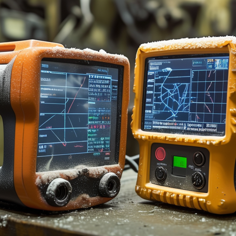
7 Best Mechanical Thermal Inspection Tools to Buy

What Mechanical Thermal Inspection Tools Measure and Why They Matter

Mechanical thermal inspection tools measure heat patterns that ordinary visual checks miss. Infrared cameras show surface temperature, thermal gradients, and uneven loading across bearings, couplings, gearboxes, and motor housings. Infrared thermometers provide quick readings, while temperature data loggers capture changes over hours or production cycles. These measurements matter because rising heat often signals friction, poor lubrication, misalignment, overload, or restricted airflow.

ISO 18434-1 identifies infrared thermography as a condition-monitoring method for machinery. The U.S. Department of Energy also reports that motor-driven systems can consume more than half of industrial electricity. A small thermal anomaly may therefore indicate both mechanical risk and wasted energy. However, surface temperature is not internal temperature. Shiny metal, airflow, distance, and incorrect emissivity settings can distort readings. I have found that a perfect-looking image can still support a poor decision.

Tips: Scan equipment under a stable load, record ambient temperature, and compare similar components. Set emissivity before measuring. Use a consistent viewing angle and distance. A thermal camera alone cannot prove failure; confirm findings with vibration, sound, lubricant condition, or current data. NFPA 70B’s maintenance approach also supports documented inspection records, so note the asset, load, temperature, and follow-up action. Recheck doubtful readings rather than forcing certainty.

Key Features to Compare Before Choosing an Inspection Tool

When comparing mechanical thermal inspection tools, start with measurement quality, not screen size. A low NETD, ideally below 40 mK, helps reveal small temperature changes around bearings and couplings. Resolution matters too. A 320 × 240 sensor can show more detail than a basic 160 × 120 model. Check the temperature range, focus method, and accuracy under changing ambient conditions. ISO 18434-1 stresses consistent thermography procedures, including emissivity and reflected temperature control.

Field usability is equally important. Look for a rugged enclosure, clear controls, replaceable batteries, and at least several hours of operating time. An IP rating helps when dust, oil mist, or moisture is present. Data storage should include radiometric images, voice notes, and location tags. Calibration traceability matters more than attractive software. The U.S. Department of Energy’s Industrial Decarbonization Roadmap reports that industry used about 32% of U.S. energy in 2020, making avoidable mechanical losses significant.

Do not ignore reporting features. McKinsey research has estimated that predictive maintenance can reduce downtime by roughly 30% and maintenance costs by 20–25%. Those figures depend on disciplined inspections, not the camera alone. I once favored the highest resolution available, then found that poor emissivity settings distorted a gearbox reading. That mistake was useful. Compare training requirements, alarm customization, inspection routes, and export formats before buying. A tool that produces impressive images but weak decisions is still an expensive compromise.

7 Best Mechanical Thermal Inspection Tools to Buy

Key Features to Compare Before Choosing an Inspection Tool

This comparison uses typical NETD values, measured in millikelvins (mK), to show thermal sensitivity. Lower NETD values can reveal smaller temperature differences, which is useful for detecting bearing friction, motor overheating, insulation problems, and early mechanical faults. Actual performance also depends on resolution, measurement range, emissivity settings, optics, calibration, and operating conditions.

Seven Essential Tools for Detecting Heat-Related Mechanical Problems

Seven Essential Tools for Detecting Heat-Related Mechanical Problems

A practical thermal inspection kit should reveal more than a bright hot spot. Start with an infrared camera, infrared thermometer, contact temperature probe, vibration analyzer, ultrasonic detector, inspection borescope, and laser alignment tool. Together, these instruments expose overheating bearings, slipping belts, blocked lubrication paths, compressed-air leaks, and shaft misalignment. The U.S. Department of Energy’s Motor Systems Market Assessment reports that motor-driven equipment uses about 68% of industrial electricity. Small thermal losses can therefore become expensive quickly.

Field experience shows that temperature alone can mislead. A shiny metal guard may reflect nearby heat, while dusty surfaces may hide a rising bearing temperature. Check emissivity, ambient temperature, load, and airflow before judging the result. Use the vibration analyzer beside the thermal camera; rising temperature with abnormal vibration often points toward lubrication failure or misalignment. The borescope can inspect inaccessible couplings, while the ultrasonic detector may reveal friction before surface heat becomes obvious. I still recheck suspicious readings. One measurement is rarely enough.

Tips: Record baseline temperatures during normal operation. Compare similar machines under similar loads. Clean the inspection area when safe. Calibrate instruments according to professional guidance, such as ISO 18436 condition-monitoring practices and NFPA 70B maintenance principles. Do not trust an impressive image without operating context. That mistake is easy to make.

How to Use Thermal Inspection Tools Safely and Accurately

Mechanical thermal inspection tools can reveal overheating bearings, loose electrical connections, blocked vents, and poor lubrication. Common options include infrared cameras, contact thermometers, thermal probes, and temperature data loggers. Each tool measures differently, so accuracy begins with choosing the right instrument for the surface and temperature range.

Work only when the machine is stable and safe to approach. Keep loose clothing, hair, and hands away from moving parts. Use barriers when inspecting hot housings or rotating assemblies. An infrared camera should be held steadily, with a clear view of the target. Clean oil, dust, and rust can distort readings. Reflective metal is especially difficult. A dull piece of tape can provide a more reliable reference surface.

Check the tool before every inspection. Confirm its battery, calibration status, and temperature settings. Compare similar components under similar loads, rather than trusting one number. I usually record ambient temperature, operating time, load, and measurement distance. Small details matter. Thermal patterns often tell more than isolated temperatures. A sudden bright area near a bearing deserves investigation, but it does not prove the exact failure. I once treated a hot surface as a mechanical fault, then found restricted airflow nearby. That mistake still influences my inspection routine. Recheck unusual results with a contact probe or a second measurement angle. Never remove guards or touch components until the equipment is isolated and cool.

Matching Each Tool to Common Mechanical Inspection Tasks

Choosing among seven mechanical thermal inspection tools depends on the defect, access, and operating condition. An infrared camera suits large motors, switchgear, bearings, and hot spots across moving equipment. A contact thermometer provides a trusted spot check when surface emissivity confuses infrared readings. For sealed housings, a borescope reveals discolored grease, scoring, or loose components without unnecessary disassembly. Small details matter.

An ultrasonic detector helps locate compressed-air leaks and early bearing friction near noisy machinery. The U.S. Department of Energy reports that compressed-air systems can waste 20% to 30% of their output through leaks. A vibration analyzer adds mechanical context by identifying imbalance, looseness, or misalignment. Use a laser alignment tool for shafts and couplings, especially after replacement work. A thermal data logger records temperature changes during long production cycles, exposing intermittent overheating that a quick inspection may miss.

The International Energy Agency reports that industry consumes about 37% of global final energy. Better inspections can therefore support both reliability and energy control. However, temperature alone does not prove failure. Reflective metal, changing loads, airflow, and poor measurement angles can mislead even experienced technicians. I have seen a cool-looking bearing hide damage beneath fresh grease. Check load conditions, compare similar components, and document readings with time, distance, and surface condition. That extra discipline is easy to skip. It should not be.

7 Best Mechanical Thermal Inspection Tools to Buy - Matching Each Tool to Common Mechanical Inspection Tasks
# Inspection Tool Best Match for Common Mechanical Tasks What It Measures or Reveals Typical Working Specification Main Advantages Important Limitations
1 Infrared Thermometer Fast Screening Checking bearings, couplings, motors, gearboxes, hydraulic fittings, and electrical-mechanical connection points for abnormal surface temperature. Non-contact surface temperature and temperature differences between similar components. Typical range: −20°C to 550°C
Typical accuracy: ±1.5°C or ±1.5% of reading
Distance-to-spot ratio: approximately 10:1 to 30:1
Lightweight, inexpensive, quick to operate, and suitable for routine inspection rounds. Useful for comparing identical components under similar loads. Measures only one spot at a time. Accuracy is affected by surface emissivity, reflective metal, distance, viewing angle, and airflow.
2 Infrared Thermal Imaging Camera Pattern Detection Locating hot bearings, uneven lubrication, overloaded components, blocked cooling passages, belt misalignment, and heat patterns across rotating machinery. A two-dimensional map of apparent surface temperature across an entire component or machine area. Typical temperature range: −20°C to 650°C
Thermal sensitivity: about 40–60 mK
Typical resolution: 160 × 120 to 320 × 240 pixels
Shows temperature distribution and hot-spot patterns. Enables safer inspection from a distance and supports visual reports with stored images. Cannot see through metal or housings. Readings depend on emissivity, reflected radiation, focus, distance, atmospheric conditions, and machine load.
3 Contact Thermocouple Thermometer Point Verification Confirming suspected hot spots on housings, pipes, bearing seats, hydraulic systems, and process equipment where a direct-contact reading is possible. Direct temperature at the probe contact point, including surface or shallow insertion measurements. Typical range: −50°C to 1,000°C, depending on probe type
Typical system accuracy: ±1°C to ±2.5°C
Common probe types: bead, surface, clamp, and immersion
Provides a useful reference for verifying infrared readings. Probe selection allows measurements on curved, flat, moving-air, or liquid-contact surfaces. Requires physical access and adequate contact pressure. Response time can be slow, and the probe may disturb delicate or moving equipment.
4 Resistance Temperature Detector Probe Stable Monitoring Continuous monitoring of bearing metal temperature, lubricant systems, motor housings, compressors, pumps, and other equipment requiring repeatable readings. Electrical resistance converted into a stable temperature reading, commonly using a platinum sensing element. Typical range: −200°C to 600°C
Common sensor class: platinum 100-ohm or 1,000-ohm
Typical accuracy: about ±0.3°C to ±1°C, depending on class and installation
Good repeatability and long-term stability. Suitable for fixed installation, alarms, data logging, and trend analysis. Usually requires wiring, signal conditioning, or a monitoring system. Installation quality and sensor placement strongly affect the result.
5 Ultrasonic Thickness Gauge Wall-Loss Inspection Measuring remaining wall thickness in pipes, tanks, pressure vessels, shafts, plates, and machine housings affected by corrosion or erosion. Material thickness calculated from the travel time of an ultrasonic pulse through the component. Typical steel thickness range: 0.8–300 mm
Typical resolution: 0.01–0.1 mm
Common accuracy: approximately ±0.1 mm plus a small percentage of reading
Often requires access from only one side. Supports non-destructive inspection and can detect progressive wall loss when readings are trended. Requires a clean, reasonably smooth surface and coupling gel. Coatings, scale, roughness, temperature, and material structure can reduce accuracy.
6 Vibration Analyzer Rotating-Machine Diagnosis Diagnosing bearing wear, imbalance, misalignment, looseness, resonance, gear defects, and lubrication-related problems in rotating machinery. Vibration acceleration, velocity, displacement, frequency spectrum, and sometimes bearing-condition indicators. Typical frequency range: 10 Hz to 10 kHz or higher
Common measurement units: mm/s RMS, g, and micrometers
Sensor type: magnetic or stud-mounted accelerometer
Detects mechanical faults before visible damage or excessive heat appears. Frequency analysis helps distinguish different failure modes. Requires correct sensor placement, machine-speed information, and baseline data. Results can be misinterpreted without knowledge of machine configuration.
7 Industrial Video Borescope Internal Visual Inspection Inspecting internal gear teeth, combustion chambers, heat exchangers, tubes, valve bodies, cavities, and areas that cannot be reached without disassembly. Remote visual evidence of cracks, pitting, wear, deposits, blockages, corrosion, and foreign-object damage. Typical insertion diameter: 4–8 mm
Typical cable length: 1–3 m
Common features: LED lighting, articulation, image capture, and video recording
Reduces disassembly time and helps document internal defects. Articulating probes can inspect around bends and behind obstructions. Primarily visual and not a substitute for dimensional or material testing. Limited lighting, probe access, oil, moisture, and curved passages can affect image quality.
Specification values are typical ranges for general-purpose instruments; actual performance depends on sensor type, calibration, installation, surface condition, and inspection environment.

FAQS

: What measurement features matter most in a thermal inspection tool?

: Choose low thermal sensitivity, ideally below 40 mK. A 320 × 240 sensor can reveal finer bearing and coupling details. Check temperature range, focus control, and accuracy during changing conditions.

Why does emissivity matter during inspections?

Emissivity affects how surfaces appear thermally. Shiny metal can reflect nearby heat and create a false hot spot. Set emissivity carefully, then compare the reading with another method.

Which tools should a practical inspection kit include?

Use a thermal camera, infrared thermometer, and contact probe. Add vibration, ultrasonic, borescope, and alignment tools. Together, they expose heat, friction, leaks, blockage, and misalignment.

Can temperature alone confirm a mechanical problem?

Usually, no. Compare temperature with vibration, load, airflow, and ambient conditions. A warm bearing may need lubrication, alignment correction, or closer observation.

What field features make an inspection tool easier to use?

Look for a rugged enclosure, clear controls, and replaceable batteries. Several hours of operating time helps during long routes. An appropriate protection rating helps around dust, oil mist, and moisture.

What data should the tool store?

Prefer radiometric images, voice notes, and location tags. These details connect a bright image with the actual machine and inspection point. Export options also matter when reports move between systems.

How can inspectors improve the reliability of their readings?

Record baseline temperatures during normal operation. Compare similar machines under similar loads. Clean the area when safe, and check suspicious readings twice. One measurement is rarely enough.

Is the highest image resolution always the best choice?

Not necessarily. A detailed image cannot fix poor settings or weak inspection habits. I once trusted resolution too much and misread a gearbox. That mistake still deserves attention.

Conclusion

Mechanical Thermal Inspection tools help identify abnormal heat patterns in machines, electrical connections, bearings, motors, pumps, and other mechanical systems before minor issues become costly failures. This guide explains what these tools measure, including surface temperature, heat distribution, temperature differences, and changes over time. It also highlights key features to compare, such as measurement range, accuracy, image clarity, portability, data storage, reporting functions, and safe operating distance.

The seven essential tools include infrared cameras, thermal scanners, infrared thermometers, contact temperature probes, thermal sensors, heat-sensitive inspection strips, and ultrasonic instruments with thermal analysis capabilities. Each tool serves different inspection needs, from quick spot checks to detailed condition monitoring. The article also presents practical advice for using Mechanical Thermal Inspection equipment safely and accurately, including correct distance, suitable environmental conditions, calibration, and protective procedures. By matching each tool to the task, users can detect overheating, friction, imbalance, poor lubrication, and other heat-related mechanical problems more efficiently.


Sienna

Sienna

Sienna is a skilled marketing professional with a deep expertise in our company’s core products and services. With a passion for innovation and detail, she plays a pivotal role in crafting insightful blog posts that not only highlight the unique features of our offerings but also provide valuable......