Choosing the right Thermal Core Module in 2026 requires more than comparing resolution or price. Buyers must connect the module’s specifications with real operating conditions, including temperature range, lens compatibility, power limits, and image-processing needs. A compact 384 × 288 core may suit handheld equipment, while a higher-resolution 640 × 512 module can reveal smaller heat differences from longer distances.
Field experience often exposes details that product sheets miss. A module may perform well in a climate-controlled laboratory but lose stability during rapid temperature changes. Ask suppliers for calibration methods, NETD results, frame-rate data, sample images, and long-term availability. Check the connector layout carefully. A few millimeters can affect the entire enclosure design.
This guide compares common Thermal Core Module types by resolution, sensor technology, integration difficulty, and application value. It considers uncooled and cooled designs, different spectral bands, and modules built for industrial inspection, security observation, research, and outdoor equipment. Reliable purchasing also requires supplier verification, traceable testing, firmware support, and clear warranty terms.
Specifications can be misleading.
Not every premium module fits every project. Cost, integration time, maintenance, and supply continuity may matter more than maximum image detail. Some recommendations may need revision as sensor performance and market pricing change. Treat this guide as a practical starting point, then validate critical choices with field trials, qualified engineers, and documented test results.
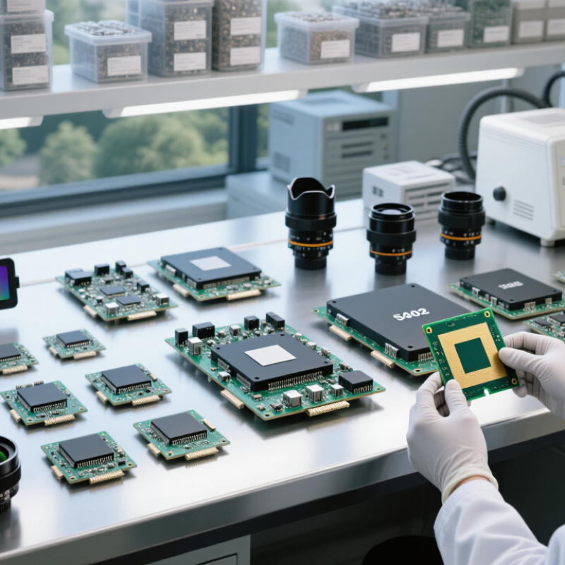
2026 Top Thermal Core Module Types Buying Guide
What Is a Thermal Core Module and How Does It Work?
A thermal core module is the imaging engine inside a thermal camera. It detects infrared energy instead of visible light. The optical lens focuses this energy onto an infrared detector. The detector changes radiation into electrical signals. A processor then applies calibration, noise reduction, and temperature mapping. The screen displays these differences as thermal images. Warm objects appear brighter or use contrasting colors. It does not truly see heat. It measures infrared radiation linked to surface temperature.
Most modules are uncooled or cooled. Uncooled cores use microbolometers and suit inspections, security, vehicles, and outdoor equipment. They start quickly and usually require less power. Cooled cores use cryogenic cooling for higher sensitivity and faster detection. They support demanding scientific, industrial, and long-distance applications. Some newer designs reduce mechanical shutters through internal calibration. That can improve reliability, though results still depend on software.
Before buying, check detector resolution, spectral range, NETD, frame rate, and temperature accuracy. Interfaces matter too. A compact module may fit a handheld device, but limited processing can restrict live image quality. Higher resolution is not always better. Lens choice, calibration, and scene contrast often matter more. In practical integration work, test samples under changing temperatures and reflective surfaces. Metal can mislead readings. Environmental sealing, startup time, power draw, and SDK support also deserve attention. One weakness remains easy to miss: published specifications may not match field performance. Test the complete system, not only the core.
In 2026, thermal core modules are available in several practical categories. Uncooled LWIR modules remain common for security, inspection, firefighting, and outdoor monitoring. They typically use microbolometer sensors operating near the 8–14 micrometer band. These modules start quickly, consume little power, and avoid mechanical cooling parts. Size still matters.
Cooled MWIR and LWIR modules serve applications requiring longer detection ranges, faster imaging, or higher temperature sensitivity. A cryogenic cooler adds cost, weight, vibration, and maintenance concerns. However, it can reveal small thermal differences across distant objects.
Integrators should examine noise equivalent temperature difference, frame rate, lens compatibility, and cooldown time before selecting a core.
Other available types include radiometric modules, dual-spectrum thermal and visible modules, shutterless designs, and compact board-level cores. Radiometric versions measure temperature within defined accuracy limits, but emissivity, distance, humidity, and reflective surfaces can distort readings. Dual-spectrum modules improve scene interpretation, yet their software and calibration demands are higher.
In field testing, a module that looks excellent in a brochure may perform poorly behind a protective window. That assumption can fail. Check the window material, calibration method, power budget, and operating temperature together.
Developers should also request sample data from real scenes, not only laboratory targets. A careful choice balances image quality, integration effort, reliability, and total ownership cost.
Thermal core modules differ most in detector physics, spectral range, and calibration design. Uncooled modules use microbolometers and usually operate without mechanical cooling. They offer lower power use, compact housing, and simpler integration. Cooled modules use cryogenic cooling for higher sensitivity and longer detection distances. They also cost more and require greater power, space, and maintenance planning. For building inspections, compact uncooled cores are often practical. For long-range observation, cooled designs may perform better.
Resolution alone does not define performance. NETD shows how clearly a module can distinguish small temperature differences. A lower NETD usually improves detail in fog, darkness, or low-contrast scenes. Frame rate affects moving targets, while spectral response influences results through glass, smoke, humidity, and outdoor temperature. Lens compatibility matters too. A wide lens captures more area, but a narrow lens offers greater target detail. These choices are easy to underestimate.
Design differences also appear in calibration and data output. Shutterless systems reduce interruptions, while shutter-based systems can support stable correction after temperature changes. Digital interfaces simplify processing, but they may increase software workload. During testing, compare startup time, image stability, power draw, and focus accuracy. Do not trust specifications alone. Real scenes are messier. A module with excellent laboratory sensitivity may show weaker contrast after rain or heat buildup. Engineers should test the complete assembly, because housing, lens, and software can change the final image.
A practical comparison of common air-cooled, liquid-cooled, and two-phase thermal core designs. Performance values are typical engineering ranges and vary with size, materials, airflow, coolant, temperature, and operating conditions.
| Thermal Core Module Type | Primary Cooling Medium | Typical Thermal Performance | Pressure Drop / Airflow Characteristics | Design and Manufacturing Features | Main Advantages | Key Limitations | Recommended Applications |
|---|---|---|---|---|---|---|---|
| Extruded-Fin Heat Sink Core | Forced or natural air | Typical air-side thermal resistance: approximately 0.10–0.50 °C/W, depending on size, fin height, airflow, and base thickness. | Low to moderate pressure drop; straight fins support predictable, unidirectional airflow. | Usually produced from aluminum extrusion; fin spacing and length are constrained by extrusion capability. | Cost-effective, robust, easy to machine, and suitable for high-volume production. | Lower surface-area density than advanced fin structures; performance decreases when airflow is restricted. | Power supplies, industrial controls, LED systems, telecommunications equipment, and general electronics. |
| Skived-Fin Heat Sink Core | Forced air or liquid in selected designs | Typically delivers lower thermal resistance than a comparable standard extrusion because it can use thinner, closely spaced fins. | Moderate to high air-side pressure drop when fin spacing is tight; requires appropriate fan selection. | Fins are cut and formed from a single aluminum or copper base, creating a continuous fin-to-base structure without a separate joint. | High fin density, good heat spreading, and flexible fin height and spacing. | Higher machining cost and potential fin damage during handling; not ideal for every high-volume application. | Compact processors, power electronics, motor drives, and space-constrained industrial equipment. |
| Bonded-Fin Heat Sink Core | Forced air | Can achieve high surface-area density and low thermal resistance when the fin-to-base bond has low thermal contact resistance. | Moderate to high pressure drop, determined mainly by fin density, height, and airflow direction. | Separate fins are attached to a base by brazing, soldering, epoxy, or mechanical bonding; supports customized geometries. | High design flexibility and good performance-to-weight ratio. | Joint quality, thermal cycling, and manufacturing consistency must be carefully controlled. | Servers, communications hardware, test equipment, and high-power air-cooled electronics. |
| Pin-Fin Thermal Core | Air or liquid | Provides strong heat transfer under turbulent flow; liquid-cooled versions generally achieve substantially lower thermal resistance than air-cooled versions. | Moderate to high pressure drop; cross-flow performance is less dependent on a single airflow direction. | Uses cylindrical, elliptical, or square pins arranged in inline or staggered patterns; commonly machined, bonded, or cast. | Good heat transfer enhancement and improved tolerance to changes in flow direction. | Higher pumping or fan power; narrow passages may be more sensitive to contamination. | Automotive power electronics, battery systems, RF equipment, and compact liquid-cooled modules. |
| Plate-Fin Liquid Cooling Core | Water, water-glycol, dielectric fluid, or other approved coolant | Typical coolant-side thermal resistance is often in the range of 0.01–0.10 °C/W for well-designed compact modules, depending on flow rate and heat load. | Moderate pressure drop; parallel or multi-pass channels allow the designer to balance heat transfer and pumping power. | Built from stacked plates, fins, manifolds, and cover plates; commonly brazed, welded, or diffusion-bonded. | High heat-removal capability, compact packaging, and scalable flow-path design. | Requires a pump, fittings, seals, coolant management, and leak-prevention validation. | Electric vehicle inverters, industrial drives, laser systems, data-center hardware, and high-power converters. |
| Microchannel Cooling Core | Air, water-glycol, refrigerant, or dielectric coolant | Very high surface-area-to-volume ratio; liquid and refrigerant designs can provide excellent heat transfer in a small envelope. | Pressure drop can range from low to high depending on channel hydraulic diameter, length, viscosity, and flow distribution. | Contains many small parallel channels formed by machining, extrusion, brazing, etching, or additive manufacturing. | Exceptional compactness, high heat flux capability, and efficient material usage. | More sensitive to clogging, fouling, flow maldistribution, manufacturing tolerances, and coolant cleanliness. | High-density computing, power semiconductors, automotive thermal systems, and refrigeration heat exchangers. |
| Vapor Chamber Thermal Core | Sealed two-phase working fluid | Offers very high in-plane heat spreading and can reduce local hot spots; performance depends on orientation, wick structure, and heat load. | No external fan or pump is required inside the sealed chamber; the attached heat sink still determines air-side resistance. | A thin sealed enclosure contains a wick and working fluid; heat is transported through evaporation, vapor flow, condensation, and capillary return. | Excellent heat spreading, low profile, low operating noise, and effective hot-spot control. | Higher cost, orientation and maximum-heat-load constraints, and strict requirements for sealing and cleanliness. | Thin computing devices, graphics modules, compact power electronics, LED lighting, and portable equipment. |
| Heat-Pipe-Assisted Thermal Core | Sealed two-phase heat pipes with air-cooled fins | Provides lower spreading resistance than a conventional solid base when heat sources and fin stacks are separated. | Air-side pressure drop is determined by the fin stack; heat-pipe operation itself does not require an external pump. | Heat pipes transfer heat from the evaporator area to remote condenser fins through phase change and capillary action. | Flexible layout, effective remote heat rejection, and good performance where direct fin placement is difficult. | Bending limits, orientation effects in some designs, added assembly complexity, and dependence on condenser airflow. | LED luminaires, notebook computers, telecom equipment, industrial displays, and distributed heat sources. |
| Cold Plate Thermal Core | Liquid coolant or refrigerant | Typical overall thermal resistance can be approximately 0.02–0.20 °C/W, depending on channel design, contact interface, flow rate, and heat flux. | Designed for a specified coolant flow and pressure-drop budget; channel geometry determines the balance between performance and pump power. | A flat metal plate contains internal channels, drilled passages, tubes, fins, or bonded structures beneath the heat source. | Excellent for direct cooling of concentrated heat loads and easy integration with mounting surfaces. | Requires reliable sealing, controlled surface flatness, thermal interface material, and system-level coolant infrastructure. | Battery packs, traction inverters, CPUs, power modules, medical equipment, and industrial laser assemblies. |
Choosing a thermal core module starts with the scene, not the product label. Uncooled modules suit many inspections, monitoring systems, and portable equipment. Cooled modules offer stronger sensitivity for small temperature differences, but they usually require higher power, tighter integration, and more careful maintenance.
Check thermal sensitivity, often listed as NETD. A lower value can reveal warmer details against a similar background. Resolution matters too. A 640 × 512 detector may separate distant targets better than a 256 × 192 model. Do not ignore frame rate. Moving machinery needs smooth imaging, while static inspection can accept slower output. Lens angle is equally important. A wide field of view helps close spaces, but it reduces detail at longer distances.
Look beyond the detector. Confirm spectral range, calibration method, temperature measurement accuracy, and supported interfaces. The module should match the host processor and available power budget. Review startup time and heat dissipation. Small housings can become surprisingly warm.
Environmental specifications deserve practical testing. Check operating temperature, humidity limits, vibration resistance, and enclosure protection. Ask for calibration records and clear testing procedures. Datasheets sometimes hide assumptions. I have seen a module perform well indoors yet lose useful contrast near reflective metal surfaces. That detail is easy to miss.
Allow margin.
Compare real scenes, not only charts. Test the module through the final window, housing, and software. A technically impressive core can still disappoint when integration changes its thermal behavior. A short trial often reveals more than a polished specification sheet.
Buyers should compare thermal core modules by use case, not headline resolution. Uncooled LWIR modules suit inspection, security, and outdoor monitoring because they need no cryogenic cooling. Cooled MWIR modules deliver better range and sensitivity, but their cooling systems increase size, power use, and maintenance. Radiometric modules add temperature data, yet accuracy depends on calibration, optics, and target conditions. MarketsandMarkets estimated the global thermal imaging market at about USD 4.3 billion in 2023, with projected growth to USD 6.5 billion by 2028. Demand is rising, but specifications still need practical testing.
Supplier comparison should begin with NETD, frame rate, resolution, calibration stability, and interface support. Ask for sample images from hot metal, wet surfaces, and low-contrast scenes. A polished laboratory image proves little. Review failure rates, replacement lead times, software documentation, and the availability of trained technical support. The module quote is only one cost. Integration, lens matching, firmware work, field calibration, and warranty handling may exceed it. An industry analysis from Yole Group also highlights growing competition in uncooled detector technologies, which can improve pricing but may create uneven quality between suppliers.
Long-term value is measurable through total cost of ownership. Record power consumption, recalibration frequency, expected service life, and image consistency after thermal cycling. A cheaper module may require more engineering hours. That is often overlooked. I would request three production samples, not one demonstration unit, and compare results under identical conditions. Suppliers should explain measurement uncertainty clearly. If they avoid that question, pause the purchase. Performance claims without test conditions are not reliable evidence.
Common options include uncooled LWIR, cooled MWIR, cooled LWIR, radiometric, dual-spectrum, shutterless, and board-level modules. Size still matters. Each type balances sensitivity, power use, cost, and integration effort differently.
Uncooled LWIR modules suit inspection, security, firefighting, and outdoor monitoring. They usually operate near the 8–14 micrometer band. They start quickly and use little power. They also avoid mechanical cooling parts.
Cooled MWIR and LWIR modules can improve long-range detection and temperature sensitivity. They may reveal small differences across distant objects. However, cryogenic coolers add weight, vibration, cost, and maintenance needs. That trade-off is easy to underestimate.
Compare NETD, frame rate, resolution, calibration stability, lens compatibility, and interface support. Also check cooldown time, power consumption, and operating temperature. A higher resolution number does not guarantee better field images. The headline can mislead.
Request sample images from hot metal, wet surfaces, and low-contrast objects. Test the module behind the intended protective window. Check reflections, image consistency, and calibration behavior. Laboratory targets are not enough.
Radiometric modules provide temperature measurements within defined accuracy limits. Readings can change with emissivity, distance, humidity, and reflective surfaces. Calibration and optics strongly affect results. The number is not automatically exact.
They can improve scene interpretation by combining thermal and visible images. However, software, calibration, and alignment requirements become more demanding. The system may need more testing and engineering time. Sometimes simpler works better.
Review failure rates, replacement lead times, documentation, technical support, and warranty handling. Calculate power use, recalibration frequency, service life, and integration labor. Request three production samples instead of one demonstration unit. One sample proves little.
The module quote may exclude lenses, firmware work, field calibration, and protective windows. Integration labor can exceed the initial hardware price. Thermal cycling may expose weaknesses later. A cheaper module may cost more overall.
This buying guide explains what a Thermal Core Module is, how it transfers or manages heat, and why its internal structure matters in modern thermal systems. It reviews the main module types available in 2026, including differences in cooling methods, core materials, size, integration, and intended applications. Readers will learn how design choices influence thermal capacity, response speed, energy efficiency, reliability, and installation flexibility.
The guide also identifies the specifications buyers should examine, such as operating temperature range, thermal resistance, power requirements, interface compatibility, durability, control features, and maintenance needs. To support informed purchasing decisions, it presents a practical approach for comparing suppliers, evaluating total costs, checking quality consistency, and estimating long-term value. Rather than focusing only on the initial price, buyers are encouraged to consider performance stability, service support, replacement availability, and lifecycle expenses when selecting the most suitable Thermal Core Module for their system.
Dianyang